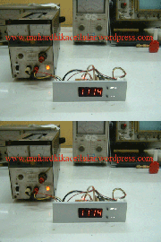
 Only by using 3pcs capacitors, 5pcs resistors, 4pcs seven-segment display, 1pc xtal, 2pcs switches and a PIC 16F84 Microcontroller / PIC 16F628, we can build this digital clock segment can use a common anode / catoda, Why do I plug the CPU in addition can also create a unique and monitor how much time we are surfing when using Time Based Quota (quota based on usage time) if we are lazy to set the time when the PC is turned on when lit hours because addressed in 00: 00 in this case it could be counter time.If you do not want to set the clock every cpu turned off or if the power off we put back up on bateray. I get Schematic from open source as follows
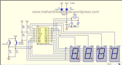
For the seven-segment display above uses common anoda. 5VDC voltage only , use the backup voltage bateray To create a path 3VDC.Make according Regulator Socket CPU can let the CPU try in any
For program using downloader Pic 16F628 as below

and to the source code DOWNLOAD HERE
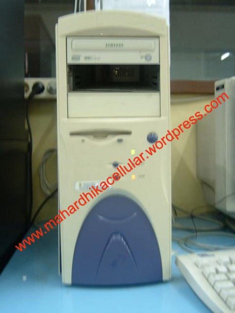
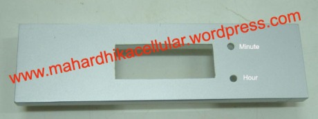
Next take the front cover on the cpu to make a hole drilled for minute , display and Hour button
After the holes will be as below
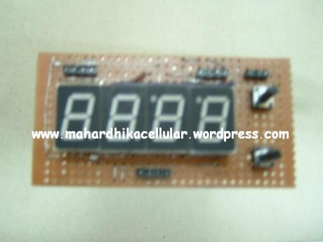
Here is a series of PCB prototypes :
1.PCB Display
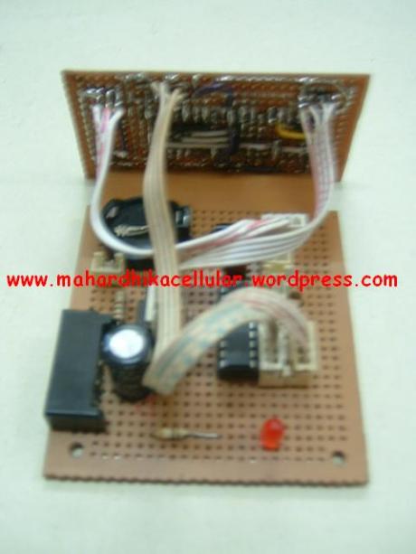
2.PCB display when combined with the main PCB is the result like this
3.Front view
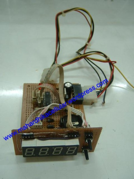
4.Connect the PCB to the panel that has been created, the previous display screen give the film (transparent dark stickers let me focus) and the test results after the IC in the contents of the program looks like this

Detail front

5.Assembly completed all the CPU to the main regulator pairs and pairs of PCB panel clock to the CPU Cassing

Though the market price of the digital clock very cheap but if our own experiment will certainly get a very useful science
* Click image for large size
Special Thanks to: Mr.Josepino http://josepino.com for open-source project
you good idea and excelent make digital clock cpu.
maaf boleh kirim source code nya ke email saya? soalnya yg di link downloadnya sudah not found.
ini email saya :
jefriwahyudi.93@gmail.com
terimakasih sebelumnya